ZSOM Mini Power and GPIOs
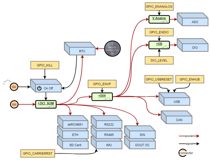
On the ZSOM-Mini different board regions can be powered separately. This can be controlled via GPIOs from the sbRIO9651. Additionally the Kill GPIO, the Go Input and alarms set on the precise_rtc can control if power is applied to the board.
The following graphic shows the dependencies in a simplified schematic view:
Examples:
- To use the general purpose high speed I/O (DIO) the ZSOM-Mini must be powered on and the GPIOs ENVP and ENDIO have to be activated.
- To use the rugged digital input (DIN) the ZSOM-Mini must be powered on. No further GIOS have to be set.
Check Out the GPIO example in the SDK to explore the funtionalities
| OUTPUTS | ||
|---|---|---|
| Name | Function | Polarity |
| ENVP | Enabled the internal 5V supply that delivers power to USB device, CAN, general purpose high speed I/O (DIO) and analog in. | TRUE = power is enabled |
| ENDIO | Enable power for general purpose high speed I/O (DIO) | TRUE = power is enabled |
| DIO_LEVEL | Choose logic levels for general purpose high speed I/O (DIO) input and output functionality | TRUE = 3.3V FALSE = 5V |
| ENANALOG | Enable power for analog in | TRUE = power is enabled |
| ADC RANGE | Switch the input range of all analog in channels. Is part of ADC FPGA driver VIs | TRUE = +-10V FALSE = +-5V |
| ENHUB | Enable power for USB device | TRUE = power is enabled |
| USBRESET | Reset USB device hub | FALSE = USB hub goes to reset state |
| CARRIERRST | Reset IMU on ZSOM Mini | FALSE = reset is active |
| KILL | Kill signal to cut the power of ZSOM-Mini | TRUE = power off |
| LED USER | Controls the ststus of the FPGA LED | TRUE = light on |
| INPUTS | ||
| Name | Function | Polarity |
| SD PWR FAIL | Error indicator of board region | |
| USB PWR FAIL | Error indicator of board region | |
| ON OFF BUTTON | Reads the status of the power on input (GO) | TRUE = pressed |
