DIO
General Purpose high speed I/O
Can be used for quasi static control signals or digital communication such as I2C or SPI
Features
| Number of channels ZSOM-Control | 16 channels |
| Number of channels ZSOM-Mini | 10 channels |
| Resolution | 1 bit |
| Range | ±3.3V or ±5V selectable per board |
| speed | 100MHz |
| max current | 20mA per channel, 150mA all channels |
| max voltage | -4V .. + 6.5V (-15V .. + 15V @ t < 10s) |
| pull up | ZSOM-Control:20kOhm on all channels ZSOM-Mini V1.1 and newer: 20kOhm on all channels ZSOM-MINI V0 .. V1: only DIO 1,2,9 and 10 have pull ups all other DIOs have a pull down of 47kOhm |
Using the IOs
In order to activate the terminal as input or output, the drivers on the NI sbRIO9651 and on the target board have to be set accordingly.
The driver on the NI sbRIO9651 can be set in the FPGA code by setting the enable signal (true = output) with an FPGA I/O Node.
The driver on the target board can be set (true = output) via a separate FPGA pin.
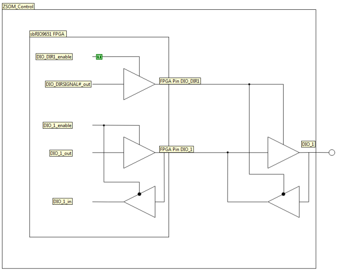
On the ZSOM-Mini Tagret GPIOs ENVP ENDIO and DIOLEVEL have to be set to enable the DIO funtionality.
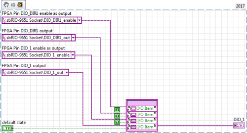
Using as output
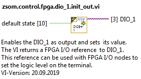
Use the vis in the getting started example to initialize all in one go:
Using as input
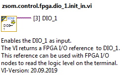
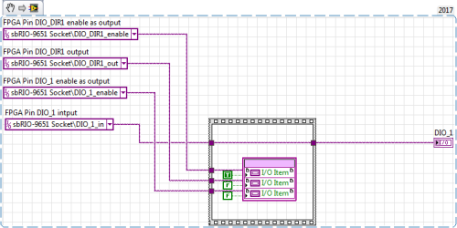
Although the pins are all configured as input at startup, it is best practice, to set the direction of the pins in the FPGA code.
Use the vis in the getting started example to initialize all in one go:
Using as bidirectional IO
For some applications such as two wire interface etc. it is necessary to switch the direction of a pin at run time.
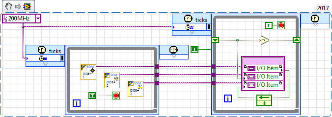
The init_io VIs in the getting started example can be used to initialize the pins accordingly.
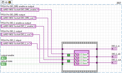
The VI returns three FPGA I/O references to DIO_1_in , DIO_1_out and DIO_1_dir.
These references can be used with FPGA I/O nodes to set and read the logic level and enable the output on the terminal.

