Table of Contents
Watchdog timer
The watchdog timer is used to reset the processor, when the software gets blocked.
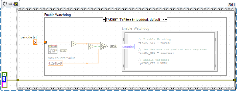
Once enabled, the 32bit watchdog timer register gets decremented every clock cycle.
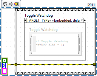
If the Toggle Watchdog C-Node is executed, the watchdog timer register is reloaded with the value given by the Enable Watchdog C-Node.
If the watchdog timer register reaches zero before it is toggled the processor is reseted and the flashed program is booted and executed from start.
Typically the “enable watchdog” is executed at program start and “toggle watchdog” is executed in the application main loop once on every iteration.

drag and drop this VI snippet into a LabVIEW block diagram.

drag and drop this VI snippet into a LabVIEW block diagram.
notes:
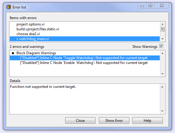
- This c-nodes work on any target, but only in compiled mode
- Once the watchdog is enabled, debugging gets complicated. For this reason add the watchdog only at the very end of a development cycle
- If you need to survey several parallel loops, insert the “watchdog_toggle” into one loop and survey the loop counters of the others
- A reset during a file function can corrupt a file system
check if a reset was caused by the watchdog
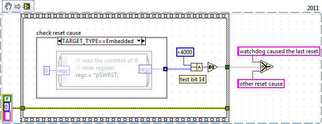
The following snippet can be used to check if the last reset was caused by the watchdog.

drag and drop this VI snippet into a LabVIEW block diagram.
The bit 14 of the reset regiter is 1, when a watchdog reset occured.
The bit is 0 when the reset was caused by other reasons.
The bit is 0 when it has been read. Hence it can only be read once per reset.
save last programm state
With this snippet you can write and read a memory space that is not initialized at boot time:

drag and drop this VI snippet into a LabVIEW block diagram.
The value read is undefined, when there was a power loss.
When a watchdog event occured or a reset signal was applied the value ramains the same as bevore the reset.
The memory space is written and read by the following functions:
- Mass storage device - Format file system - Firmware update
The usable memory space is 16bytes long. With U32 an I32 Values 4 values can be written at the following locations:
0xFF800000
0xFF800004
0xFF800008
0xFF80000C
